Velocity is the second of the three base products that are produced by pulsed Doppler radars and is used to indicate the motion and speed of targets. Since the radar is at a fixed location, it can only measure how fast a target is moving toward or away from the radar itself. This is known as radial velocity, and it differs from true velocity. This is important because radial velocity is almost always less than true velocity. Let’s take a closer look at how radial velocity works:
Remember from earlier that the farther we get away from the radar, the higher the beam is scanning. This becomes particularly important when examining velocity data. At 100 miles from the radar, the velocity data that we’re looking at is nearly 12,000 feet above the ground.
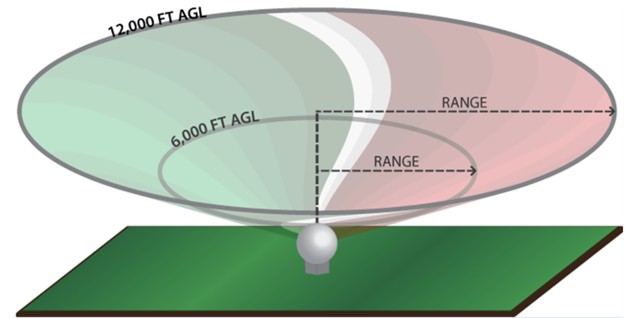
There are three basic principles with regard to radial velocity:
- Radial velocity will always be less than or equal to actual target velocity.
- Radial velocity will be equal to the actual target velocity only when the target motion is directly toward or away from the radar.
- When the target motion is perpendicular to the radar beam, the radial velocity will be zero.
So what exactly is radial velocity?
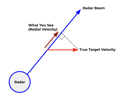
In the example below, we see our radar scanning off to the northeast and striking a target, but this target (red arrow) is moving from west to east, not directly away from the radar. Since the target is not moving directly away from the radar, the radar beam will never be lined up with the target, so it cannot sample its true velocity. Instead, it only samples a portion of the true velocity. This portion of the true velocity is determined by the angle between the radar beam and the target motion. The greater the angle, the less of the true velocity that is sampled. In the example below, the radial velocity is about 80% of the true velocity.
Basic Radial Velocity Example
In this hypothetical example, the true winds are blowing from west to east at all points on the radar screen and at the same speed (yellow arrows). By convention, green colors indicate winds blowing toward the radar and velocity values are negative. Red colors indicate winds blowing away from the radar and velocity values are positive. This convention comes from the early days of Doppler radar when radars pointed vertically. Winds blowing down were negative and winds moving upward were positive.
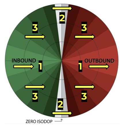
Notice that when the radar beam is pointed due west or east (points #1), the radial velocity is nearly equal to the true velocity of the target. When the radar beam is pointed due north or south (points #2), the radial velocity is zero. This is because the radar beam is perpendicular to the target motion and no component of the true velocity is moving directly toward or away from the radar. This line of zero velocity is known as the zero isodop. Everywhere else on the radar screen (points #3), the radar will sample a portion of the true velocity. The radial velocity is dependent upon the angle between the radar beam and the true velocity.
So what about direction? How do we determine the wind direction?
In this hypothetical example, we’ll take a look at determining wind direction. Unlike the example above, in this case, the wind direction changes with height. We’ll use the zero isodop (gray line) to help determine the direction. Remember that along the zero isodop, the radar beam is perpendicular to the true velocity. Because of this, we can determine the direction of targets along this line. If you draw a line from the radar (center) to any point along the zero isodop (gray line), the wind direction will be perpendicular to the line. Winds will also blow from the inbound side to the outbound side.
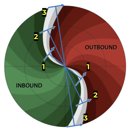
At point #1, located at the first range ring (for this example we’ll assume that this first ring is where the radar beam is 4,000 feet above the ground), if we draw a line from the radar to a point along the zero isodop, then our wind direction will be perpendicular to this line, from inbound to outbound. So, at this point, our wind direction is southwest. At point #2 (8,000 feet above the ground), our wind direction is west-southwest. And at point #3 (12,000 feet above the ground), our wind direction is nearly due west. So, we can see that our winds are changing direction as we go higher up into the atmosphere. This is called wind shear and can play an important role in severe weather.
Base Velocity
Unlike reflectivity, there is no composite velocity product. The radar produces a velocity product for each elevation angle that is scanned. In addition, it computes a “storm relative velocity” product. We’ll look at both of these and identify when we should use one over the other.
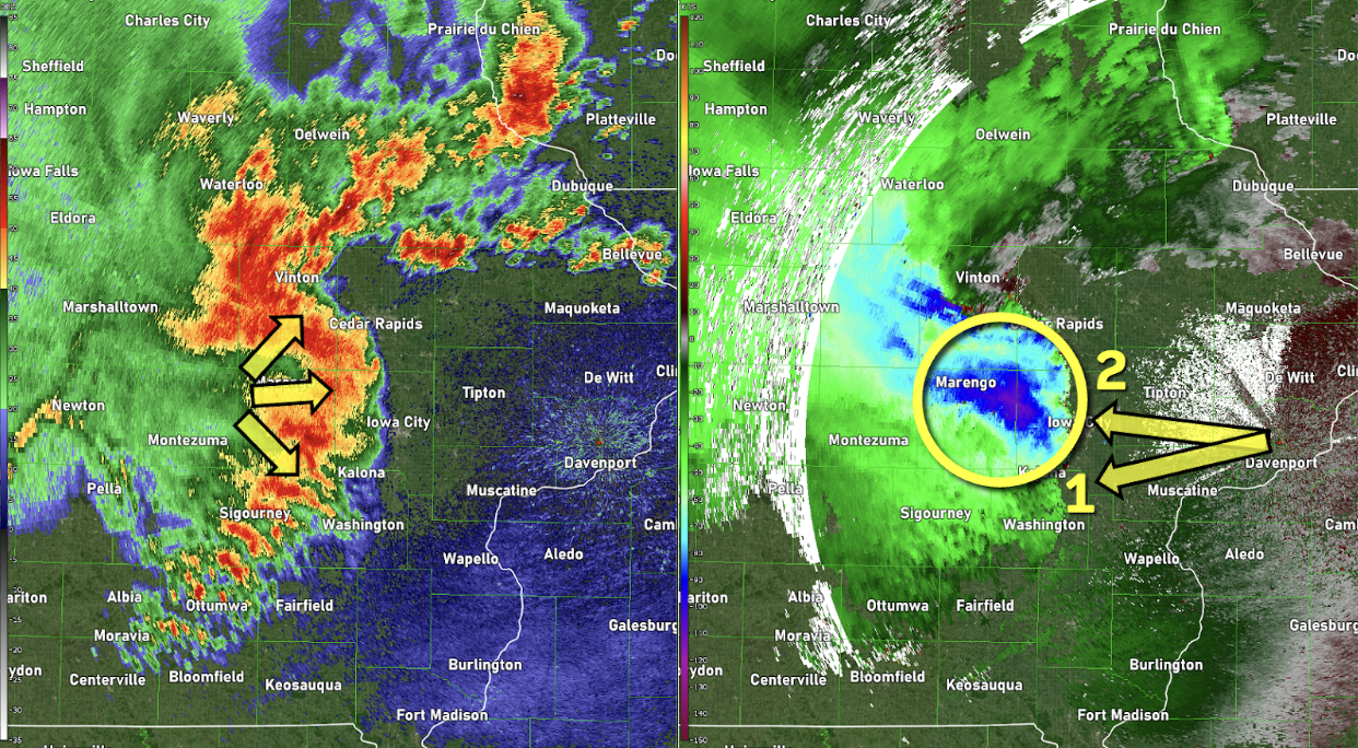
In the velocity image above, notice the large area of blue colors. These are winds in excess of 90 mph and they’re occurring right along the apex of the bow. Notice how the velocity drops off significant just to the south (arrow #1). While we could make the assumption that the winds are not as strong here, we have to keep in mind that the true velocity is not being fully sampled in this area, as compared to arrow #2. At arrow #2, the radar beam is sampling nearly all of the true velocity, as these storms are moving directly toward the radar. This storm system produced widespread 80 to 100 mph winds with extensive damage across eastern Iowa.
What about tornadoes?
Doppler radar really excels at tornado detection because tornadoes rotate in a complete circle, allowing there to be a component of the wind that will always blow directly toward or away from the radar, no matter where it’s located. Let’s take a closer look!
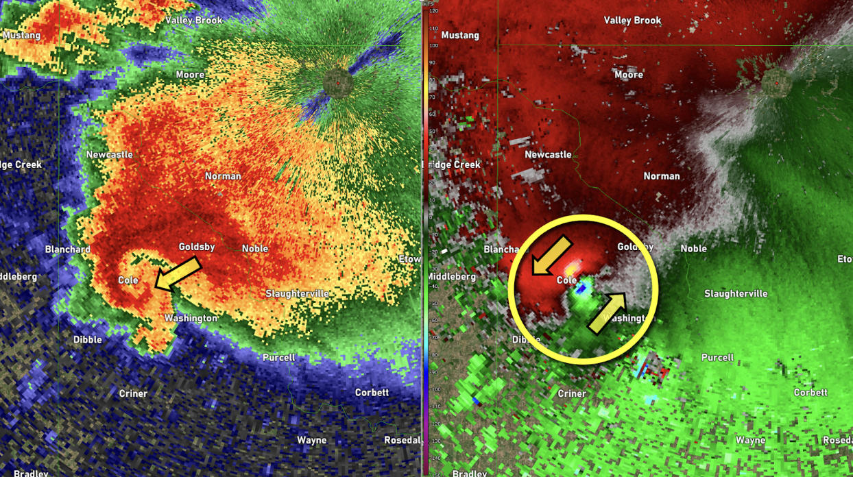
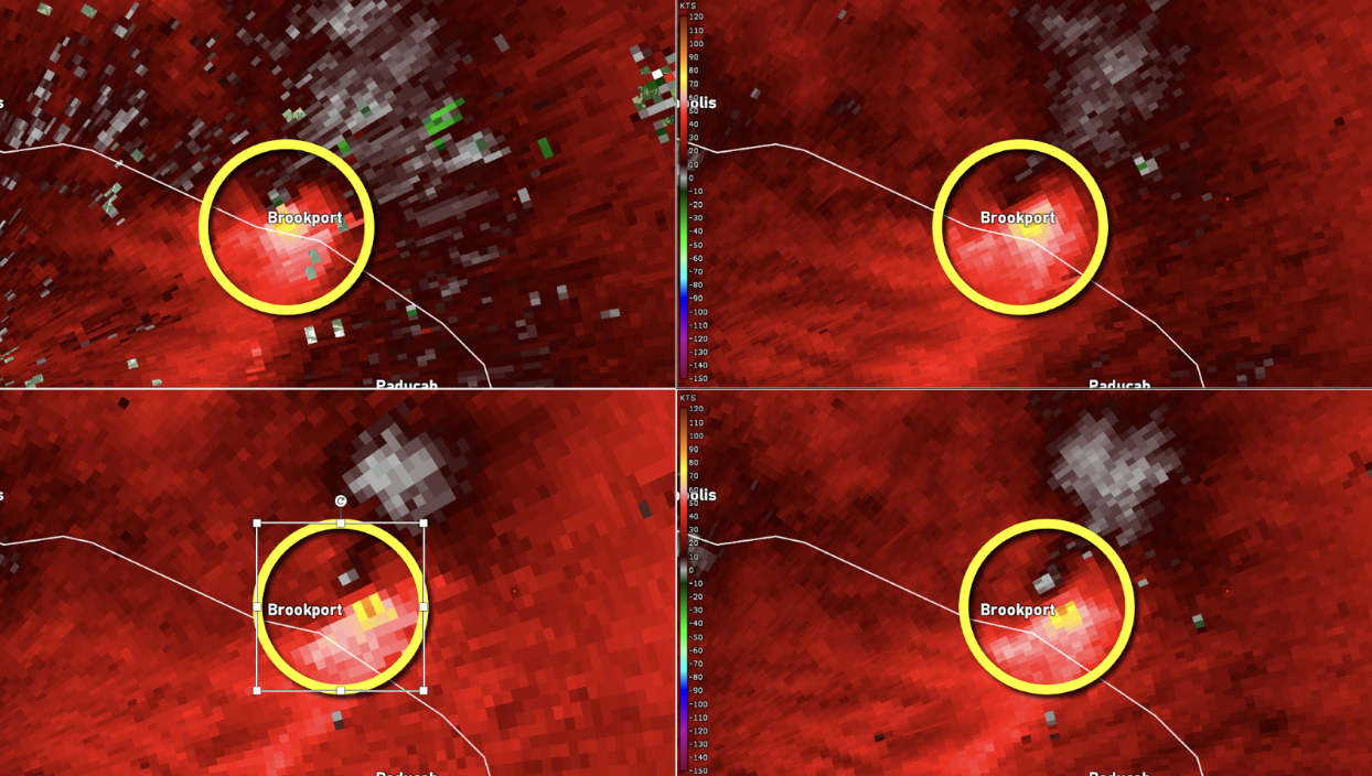
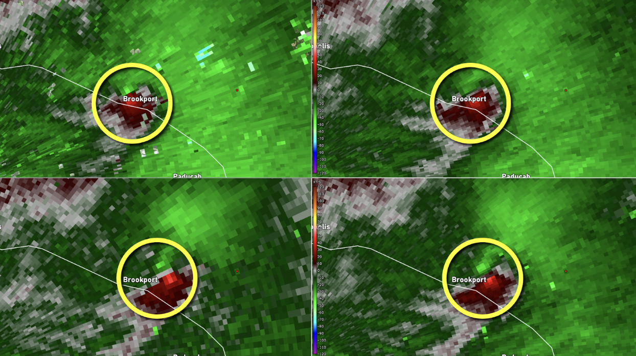
The image above shows a classic tornado-producing supercell thunderstorm. Both the reflectivity and velocity images are used by forecasters to issue severe thunderstorm and tornado warnings. Based on both of the images above, a tornado warning would be issued in this case. The very bright inbound/outbound couplet is a common feature indicative of a possible tornado. We say “possible” because the radar doesn’t actually detect tornadoes. Remember that the radar beam quickly rises above the surface, so we’re actually detecting the very strong rotation associated with a tornado. This very strong rotation is known as a tornado vortex signature or TVS. Warning forecasters usually need more than just the lowest elevation angle when issuing warnings, so let’s take a look at what the velocity data looked like with this storm from multiple elevation angles.
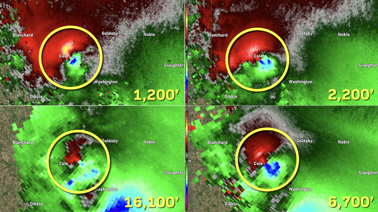
What about Storm Relative Velocity? When would I use that?
Storm-relative velocity is computed from the base velocity product and can be helpful in certain situations. The radar only samples radial velocity (the portion of true velocity that is moving directly toward or away from the radar), which includes not only the winds within a storm, but also the storm motion itself. For example, let’s say a storm has 50 mph winds in it and let’s assume that this storm is moving directly toward the radar at 20 mph. The base velocity product will indicate 70 mph winds. Sometimes this can make it difficult to isolate areas of rotation when storms are moving very quickly. In order to show the winds relative to the storm, we need to subtract out the storm motion. That’s what the storm-relative velocity product does. It uses an average storm motion speed and subtracts this out from the velocity product. Let’s take a look at what this looks like!
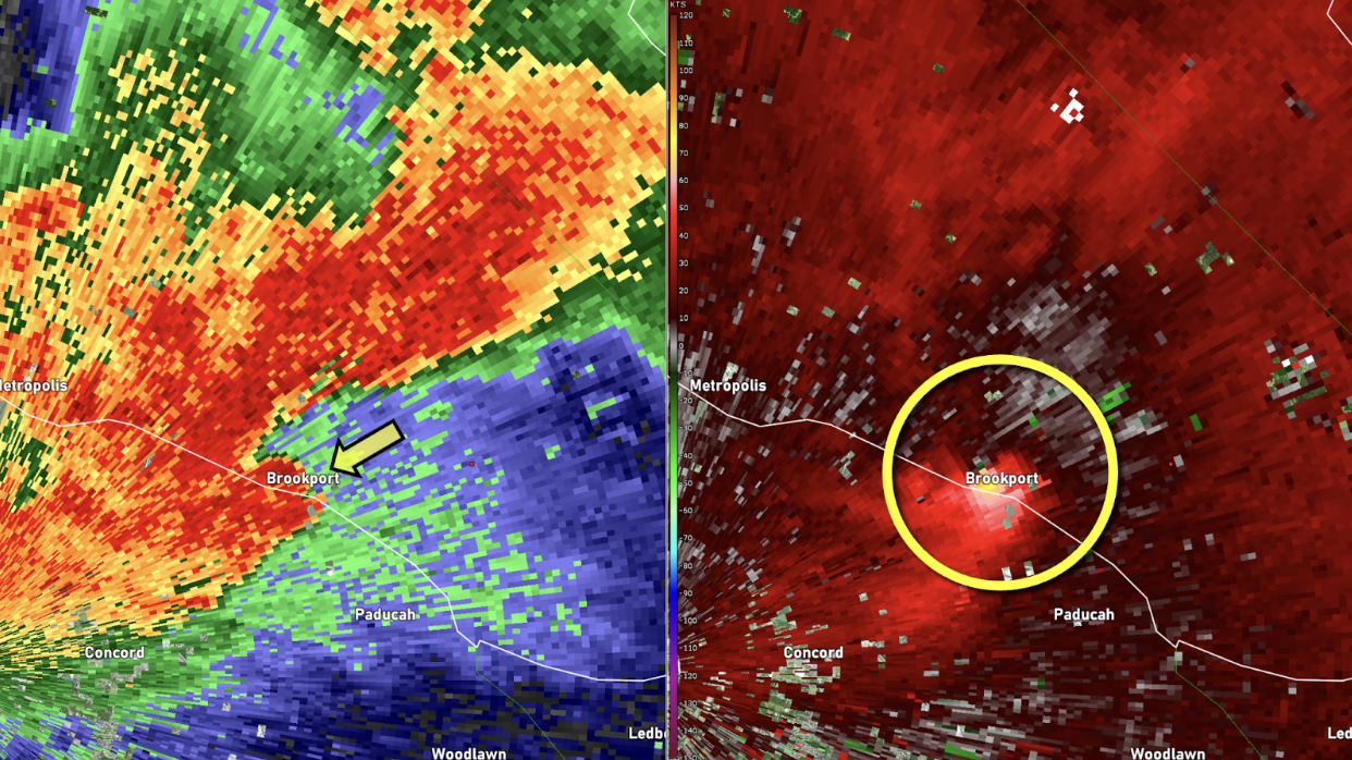
In the above image, we can see a classic hook shape, which should alert us to potential rotation within this storm, but when we look at the base velocity image, we see a large area of outbound winds and very little in the way of inbound winds. This image does not look like the one of the Oklahoma tornado above. An experienced warning forecaster will quickly identify this as an area of rotation, but why doesn’t it look as impressive as the Oklahoma tornado? The reason is because this storm was moving at 55 mph away from the radar, so the outbound winds look very strong, but the inbound winds appear to be masked. Is there anything we can do to help us out? Well, let’s take a look at the Storm Relative Velocity product. Remember that this product subtracts the storm motion out. Let’s get rid of that 55 mph storm motion and see if there’s any rotation that’s apparent.
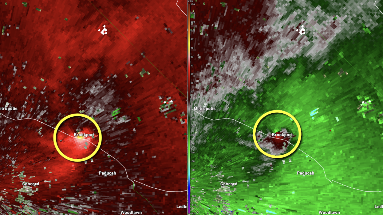
Once we subtract out the fast storm motion, the rotation becomes more apparent. Storm relative velocity can be very helpful when trying to identify areas of rotation within fast moving clusters of storms. As was mentioned above, forecasters usually look for vertical continuity in the velocity data to warn for tornadoes. Let’s take a look at base velocity from four different elevation angles of this storm, and we’ll compare it to the storm relative velocity product.
